

Membrane separation splits a feed into permeate and retentate wherever water, chemicals, food ingredients, pharmaceuticals, or metals must be recovered or removed. It appears in desalination, water reuse, dairy, ultrapure water, hydrometallurgy, and solvent recovery. Yet "membrane separation" describes a family of processes, not a single product. Two elements with similar housings can differ in polymer, pore size, surface charge, driving force, and packaging. That is why searching for "the best membrane" rarely helps.
Membrane separation classification groups these processes by the question they answer: what is the product, what is the membrane made of, what drives transport, how tight is the cut, how is the barrier structured, and how is it packaged. The six lenses below are complementary views of one specification; used in sequence, they narrow a crowded market to a short list worth testing.

membrane separation classification framework
The classification of membranes primarily encompasses six dimensions, as illustrated in the left figure: separation target, membrane material, driving force, separation precision, membrane structure, and membrane module structure. Below, the author will provide a detailed breakdown of these categories.
1. By Separation Target
----What Must Leave, and What Must Stay?
The first lens is process economics. If permeate is the product, the job is purification: water passes while salts, colloids, or organics are retained. Reverse osmosis for ultrapure water is the clearest example. If retentate is the product, the job is concentration: water leaves as permeate while valuable or problematic species stay behind. A membrane that concentrates a metal-bearing stream is a concentration membrane, even if its polymer and pores resemble NF.
If both streams have value, the job is separation. If the target is a narrow fraction between two cutoffs, the job is extraction: material passes a looser membrane but is retained by a tighter one, so the product is the fraction between the two limits. Each label changes the metric. Purification is judged on permeate quality, concentration on recovery and retentate strength, and separation on both streams.
YIME's specialty membranes show how one technology changes role. Its precious-metal membrane retains metal values in the concentrate, so it works as a concentration membrane. Its reverse osmosis membrane is designed around the permeate-pure water-so it is a purification membrane. Different products, different metrics.
2. By Membrane Material
----Organic, Inorganic, and Metal
The second lens is chemistry. Organic membranes use polymers such as polysulfone (PSf), polypropylene (PP), polyacrylonitrile (PAN), polyvinylidene fluoride (PVDF), polyethersulfone (PES), cellulose acetate (CA), aromatic polyamide, and piperazine-based polyamide. They dominate water treatment because they are inexpensive, pack into high-area modules, and run at lower pressures than ceramics. Their limits are practical: oxidants, solvents, extreme pH, or heat attack the polymer; mechanical strength is limited; and cleaning windows are narrower.
Inorganic membranes are typically ceramic, glass, or silicates, with selective layers of alumina, zirconia, titania, or silica. They tolerate high temperatures, aggressive cleaning, and harsh chemicals, and can be backflushed hard. In exchange, they are heavier, costlier, brittle under thermal shock, and pack less area per unit volume. Metal membranes are a smaller group: dense palladium alloys separate hydrogen, and porous stainless steel serves as a support. Metal-oxide membranes are usually grouped with ceramics.
The families are converging. Organic membranes gain charged coatings, mixed-matrix fillers, and composite layers; ceramics gain thinner layers and higher packing density. Aromatic polyamide still dominates reverse osmosis, while NF, UF, and MF offer more polymers and surface chemistries. That variety lets a membrane be adapted to a duty, not picked by pore size.
YIME's nanofiltration line is an example: starting from a nanofiltration substrate, the company uses a multi-dimensional interlayer-coordination strategy to tune separation between monovalent and divalent metal ions. No single polymer is universally better; chemistry can be engineered around a separation problem.
3. By Driving Force
---What Pushes the Separation?
Every membrane process needs a gradient-pressure, partial pressure, osmotic pressure, concentration, electrical potential, or temperature. That gradient determines equipment, energy, and fouling mode more than pore size does.
| Driving force | Typical process | What moves | Common duty |
|---|---|---|---|
| Transmembrane pressure | MF, UF, NF, RO | Water and small solutes | Water treatment, concentration, pretreatment |
| Partial-pressure difference | Gas separation, pervaporation | Specific gas or vapor species | Hydrogen recovery, VOC removal, dehydration |
| Osmotic-pressure difference | Forward osmosis | Water | Difficult feeds, draw-solution processes |
| Concentration difference | Dialysis | Small solutes | Blood purification, some chemical recovery |
| Electrical-potential difference | Electrodialysis (ED), EDI | Charged ions | Brackish water, acid/base recovery, ultrapure water |
| Temperature difference | Membrane distillation | Water vapor |
High-salinity brine, thermal integration |
Pressure-driven processes are familiar, but not the whole family. Electrodialysis uses ion-exchange membranes and an electric field to remove charged species without a tight polymer. Membrane distillation passes water vapor through a hydrophobic membrane, so it can treat brines that would foul RO. Forward osmosis uses an osmotic gradient instead of a pump, though it still needs draw-solution recovery. A membrane that excels under pressure may be irrelevant under another gradient.
For the YIME-AgR100-8040 Silver Ion Concentration Membrane, the driving force is pressure: 2.5 MPa (363 psi). That places it at the high-pressure end of nanofiltration, closer to reverse osmosis than to low-pressure ultrafiltration. The pressure follows from the tight 100 Da cut and the need to overcome osmotic pressure and concentration polarization in concentrated cyanide streams.
4. By Separation Precision
---From MF to RO, With Detours
Separation precision is the most-used lens and the most oversimplified. Microfiltration (MF) removes suspended solids, bacteria, and algae at 0.1–10 µm. Ultrafiltration (UF) operates at roughly 1–100 nm, retaining colloids, proteins, oils, and macromolecules. Nanofiltration (NF) sits at about 0.5–2 nm, rejects many multivalent ions and small organics, and passes some monovalent ions. Reverse osmosis (RO) is tighter, rejecting most dissolved ions while passing water.
These ranges are indicative. Real retention depends on charge, hydrophilicity, morphology, feed concentration, pH, temperature, and the molecular weight cut-off (MWCO) test method. MWCO is usually assigned with neutral probes, so it cannot by itself predict rejection of a charged ion. Two "NF" membranes can behave very differently on the same brine.
| Class | Indicative cut-off | Typical retention | Common applications |
|---|---|---|---|
| MF | 0.1–10 µm | Suspended solids, bacteria, algae | Clarification, pretreatment, wastewater |
| UF | 1–100 nm (≈1–1,000 kDa) | Colloids, proteins, oils, macromolecules | Dairy, food, reuse, oil–water separation |
| NF | ≈0.5–2 nm (often 100–1,000 Da) | Multivalent ions, dyes, small organics | Softening, dye–salt separation, metal recovery |
| RO | <0.5 nm (≈<100 Da) | Most ions and small molecules | Desalination, ultrapure water, concentration |
| ED / EDI | Not a pore-size cut-off | Charged ions | Brackish water, acid/base recovery, ultrapure water |
| MD | Not a pore-size cut-off | Water vapor | High-salinity brine, water recovery |
ED, EDI, and MD appear in the same table because buyers compare them side by side, but they are not pore-size cousins. ED and EDI use electrical potential; MD uses a thermal gradient.
5. By Membrane Structure
---What the Cross-Section Reveals
Membrane structure describes how the barrier is built. A symmetric membrane is roughly uniform through its thickness. An asymmetric membrane has a thin selective skin on a more open support of the same polymer. A thin-film composite (TFC) goes further: an ultrathin selective layer is coated onto a porous support, so barrier chemistry and support mechanics can be optimized independently. Most RO and many NF membranes are composites for this reason.
Structure also covers porosity and surface chemistry. MF and UF membranes are porous; RO membranes are dense and rely on solution–diffusion, not sieving. NF sits between them, with pores small enough that charge and dielectric effects matter. Charged, mixed-matrix, and interlayer-tuned membranes try to decouple selectivity from permeability. The cross-section sets the trade-off between flux, rejection, fouling, and strength.A high-flux composite may fail if the feed contains abrasives, or if cleaning agents attack the interlayer. A ceramic membrane may suit a high-solids, high-temperature duty even at lower flux.
6. By Element Structure
---How the Membrane Is Packaged
The final lens is the module that turns a flat membrane into an element. Spiral-wound modules roll flat sheets around a permeate tube, with spacers creating flow channels. They offer high packing density, predictable scale-up, and lower cost per square meter, which is why they dominate RO and NF. Hollow-fiber modules use thousands of fine fibers for high area per volume, but foul easily and are often backwashed. Tubular modules handle high solids and viscous feeds but pack less area. Plate-and-frame modules are easy to clean and suit small, dirty, or high-value streams. Ceramic monoliths combine many channels in one block for harsh chemical and thermal duties.
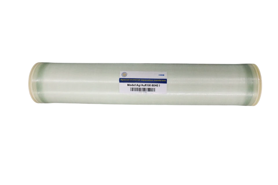
The YIME-AgR100-8040 uses a spiral-wound 8040 element-8.0 inches in diameter, 40 inches long-with 400 ft² (37.2 m²). That format fits a clean, prefiltered, high-pressure stream and packs area into a standard vessel. It is not right for feeds with large solids or high fouling loads; tubular or plate-and-frame designs may be more robust, at higher capital cost.
Element structure causes pilot-plant surprises. A membrane that performs well in a flat-sheet test can lose flux in a spiral-wound element when the feed spacer fouls, pressure drop rises, or concentrate flow is too low. Maximum differential pressure and minimum concentrate-to-permeate ratio therefore deserve as much attention as rejection. They define the hydraulic envelope in which test data become performance.


